
Abstract
Energy storage modules based on lithium chemistry are fundamental to the operation of modern unmanned aerial vehicles (UAVs). Although these batteries are routinely charged in field and laboratory environments, the charging process itself is governed by a set of electrochemical, thermal, and operational constraints that are often underestimated. Deviations from appropriate charging conditions accelerate structural degradation, reduce available capacity, and increase the likelihood of catastrophic failure. This study re-examines UAV battery charging from a systems-engineering perspective, emphasizing the interaction between cell chemistry, charging algorithms, environmental boundaries, and mission-level requirements. The analysis consolidates engineering principles into a unified framework suitable for UAV researchers and operators.
Index Terms— UAV energy systems, lithium-based batteries, charge regulation, thermal constraints, operational safety.
I. Introduction
Rechargeable lithium batteries have become the dominant power source for small aerial robotic platforms due to their favorable mass-specific energy and ability to sustain high transient loads. Despite their ubiquity, the charging of these batteries remains a non-trivial engineering task. The charging process is constrained by the kinetics of lithium intercalation, the stability of the solid–electrolyte interface (SEI), and the thermal behavior of the cell stack. These constraints impose strict limits on voltage, current, and temperature during charging. As UAVs transition from recreational devices to mission-critical assets, the need for rigorously defined charging procedures becomes increasingly important. This paper analyzes the charging process from a multi-layered engineering viewpoint, integrating electrochemical fundamentals with UAV operational requirements.
II. Battery Architectures in UAV Platforms
A. Polymer-Electrolyte Pouch Cells
Polymer-electrolyte pouch cells, commonly referred to as LiPo batteries, employ laminated electrode stacks and a gel-like electrolyte. Their mechanical flexibility enables high energy density but also increases susceptibility to deformation-induced failure. The voltage window is tightly constrained by electrolyte stability, and exceeding the upper threshold initiates irreversible side reactions.
B. Cylindrical and Prismatic Lithium-Ion Cells
Li-ion cells with rigid enclosures exhibit improved structural robustness and longer cycle life. Their electrochemical behavior is governed by intercalation dynamics within layered or spinel cathode structures. Although their discharge capability is lower than that of LiPo cells, their thermal stability and predictable aging characteristics make them suitable for endurance-oriented UAVs.
C. Battery Packs with Embedded Management Electronics
Advanced UAV platforms integrate battery management systems (BMS) that supervise cell voltages, temperatures, and balancing operations. These embedded systems enforce operational boundaries and provide diagnostic information, but they do not eliminate the need for controlled charging environments.
III. Pre-Charging Evaluation
A. Structural Integrity Assessment
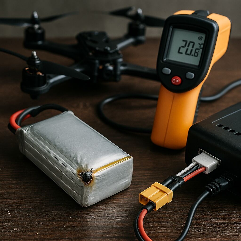
Before initiating charging, the battery must be evaluated for mechanical anomalies. Deformation, gas accumulation, or electrolyte residue indicates compromised internal structure. Such conditions alter internal impedance and can trigger thermal instability during charging.
B. Thermal State Verification
The temperature of the cell stack strongly influences charge acceptance. Low-temperature charging slows lithium diffusion and promotes metallic lithium deposition, while elevated temperatures accelerate parasitic reactions. A thermally equilibrated state is therefore required prior to charging.
C. Charger Configuration Consistency
For packs without embedded management electronics, the charger must be configured to match the pack’s cell count and chemistry. Incorrect configuration alters the voltage ceiling or current profile, leading to accelerated degradation or immediate failure.
IV. Charge Regulation Mechanisms
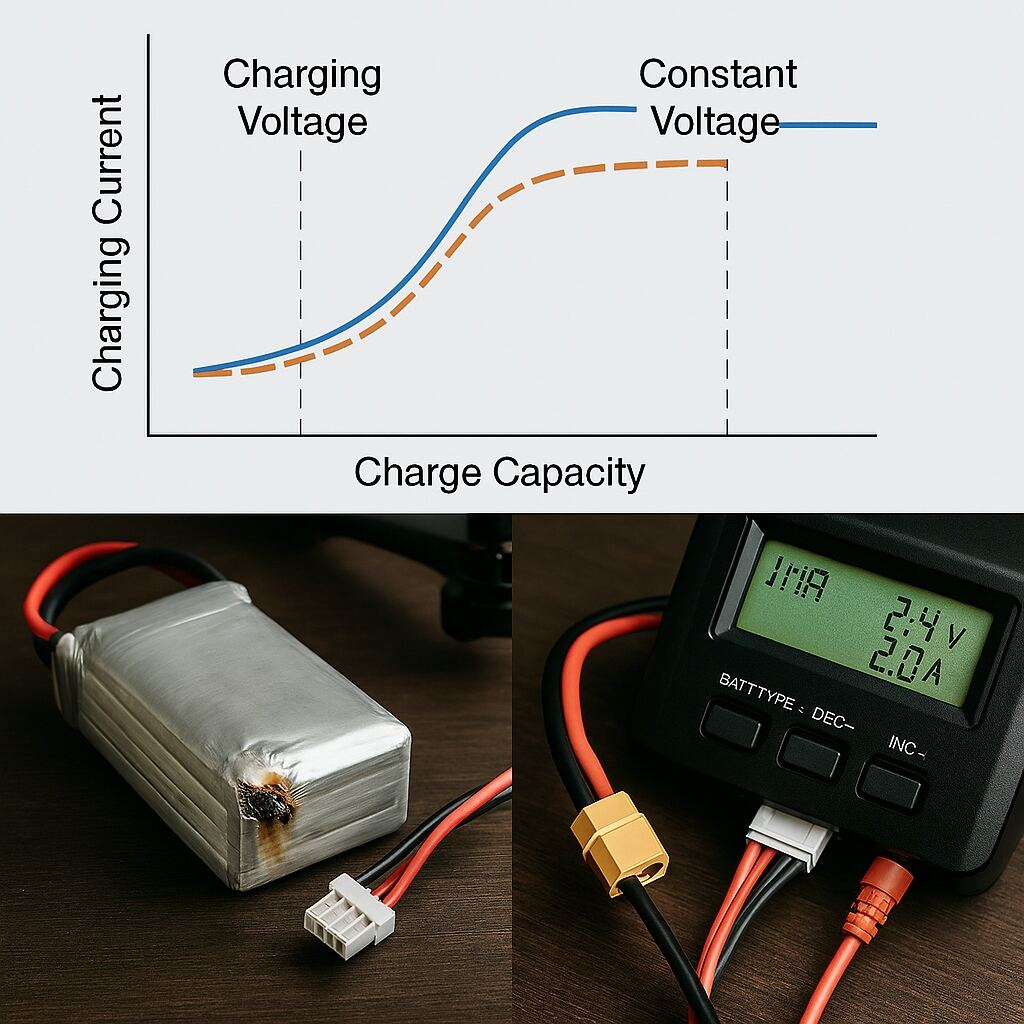
A. Two-Stage Charge Control
Lithium-based batteries are typically charged using a two-stage regulation scheme. The initial stage maintains a constant current, allowing the cell voltage to rise according to its internal impedance. Once the voltage reaches the upper threshold, the charger transitions to a constant-voltage stage, during which current gradually decreases. This approach minimizes stress on the electrode–electrolyte interface.
B. Inter-Cell Equalization
Multi-cell packs require equalization to prevent divergence in cell voltages. Without balancing, the weakest cell dictates the usable capacity, and the strongest cell risks over-voltage during charging. Equalization circuits dissipate or redistribute charge to maintain uniformity across the pack.
C. Current Selection and Degradation Considerations
The charging current is typically expressed as a fraction of the pack’s nominal capacity. Higher currents reduce charging time but increase thermal load and accelerate SEI growth. Lower currents reduce degradation but extend turnaround time, creating a trade-off between operational tempo and battery longevity.
V. Charging Procedure and Environmental Requirements
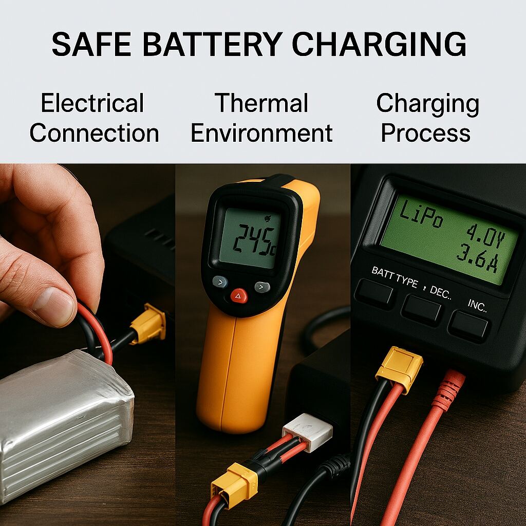
A. Electrical Interface and Connection Order
Charging requires secure connection of both the main power leads and, for LiPo packs, the balancing connector. Improper sequencing or loose connections introduce resistive heating and voltage instability.
B. Physical Charging Environment
The charging environment must minimize thermal accumulation and eliminate ignition sources. Non-flammable surfaces and adequate airflow are essential. Batteries should not be placed in confined spaces where heat cannot dissipate.
C. Real-Time Parameter Monitoring
During charging, temperature, voltage uniformity, and current decay must be monitored. Deviations from expected behavior indicate internal anomalies such as rising impedance or localized heating.
D. Post-Charge Stabilization
After charging, the battery undergoes a brief relaxation period during which internal gradients dissipate. This stabilization improves voltage accuracy and reduces thermal stress before deployment or storage.
VI. Safety Constraints and Failure Pathways
A. Thermal Instability Mechanisms
Thermal runaway arises when exothermic reactions exceed the cell’s ability to dissipate heat. Over-voltage, internal short circuits, and mechanical damage can initiate such reactions. Preventive measures include controlled charging environments and continuous monitoring.
B. Environmental Sensitivity
Humidity, direct solar radiation, and enclosed spaces alter the thermal boundary conditions of the battery. Charging under such conditions increases the likelihood of exceeding safe operating limits.
VII. Charging of Managed Battery Systems
A. Embedded Supervisory Functions
Smart batteries incorporate microcontrollers that regulate charging parameters, monitor cell health, and enforce safety limits. These systems reduce operator burden but still require adherence to environmental and thermal constraints.
B. Operational Workflow
Charging typically occurs through a dedicated interface or hub that communicates with the embedded controller. The system autonomously manages balancing and protection functions.
C. Operational Limitations
Despite their sophistication, smart batteries remain sensitive to temperature extremes and prolonged high-state-of-charge storage. Their protective functions cannot compensate for improper handling.
VIII. Operational Errors and Their Engineering Implications
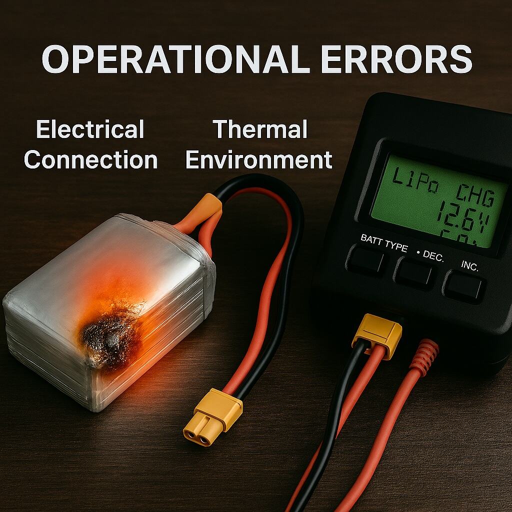
Common operational errors include initiating charging immediately after high-load discharge, using damaged connectors, applying excessive current, and charging in thermally unstable environments. These practices accelerate impedance growth, reduce cycle life, and increase the probability of failure.
IX. Strategies for Extending Battery Service Life
A. Moderated Charging Rates
Lower charging currents reduce thermal stress and slow degradation mechanisms.
B. Controlled Storage State
Maintaining the battery at an intermediate state of charge during storage minimizes chemical aging.
C. Fleet-Level Rotation
Distributing usage across multiple packs prevents uneven aging and improves overall fleet reliability.
D. Electrical Interface Maintenance
Periodic cleaning of connectors reduces resistive losses and improves charging efficiency.
X. Charging Under Non-Standard Conditions
A. Low-Temperature Operation
Charging at low temperatures requires pre-heating and reduced current to avoid lithium plating.
B. High-Temperature Operation
Charging in hot environments necessitates active cooling or relocation to thermally stable areas.
C. Field Charging Constraints
Portable power sources must provide stable voltage and low-distortion waveforms to avoid charger malfunction.
XI. Mission-Oriented Charging Management
A. Operational Planning
Mission-critical UAV operations require structured charging schedules, including pre-mission full charging, inter-mission cooling, and post-mission storage conditioning.
B. Health Monitoring
Tracking internal resistance, temperature history, and voltage deviation enables predictive maintenance and early detection of failing packs.
XII. Conclusion
The charging of UAV batteries is a multi-constraint engineering process shaped by electrochemical behavior, thermal dynamics, and operational requirements. Effective charging protocols enhance safety, extend service life, and improve mission reliability. A systems-level understanding of these constraints is essential for both researchers and practitioners in UAV energy management.
